

Layout
GVPM is a special closed-circuit wind tunnel, arranged in a vertical layout with two test rooms located on the opposites sides of the loop. The first one is located in the lower part of the loop and is suitable for Low Turbulence tests. The second one, larger, is located in the upper part of the loop and it is intended for civil, environmental and energy engineering testing (the Boundary Layer Test Section). Due to this unique feature, GVPM offers the widest possible range of test arrangements and alternatives. The facility is powered by a flow generator array of 14 fans, each one featuring a diameter of 1.8 m and an adsorbed power of 100 kW for a total power of 1.4 MW. The fans are organized in two rows of seven 2x2m independent cells. Independent inverters drive the fans allowing for continuous control of the rotation speed of each fan to obtain the desired wind speed in the test section.
downstream of the fans two corners fitted with vanes conducts the flow to the upper level of the facility in the opposite direction. The flow is than cooled by a heat exchanger that is placed just downstream of bend number 2 and, after a grid, enters the boundary layer test section.
A second set of two corners fitted with vanes conducts the flow back to the lower level where, after a 2 meters long settling chamber, it passes a honeycomb screen and a set of three wire nets featuring different porosity to reduce axial and lateral turbulence and to promote a more uniform axial flow. A two-dimensional contraction cone with area ratio 3.46:1 reduces the duct section to fit the low turbulence test section size. Finally a short diffuser expands the duct section back to the fans array size.
The optimization and assessment of the facility layout and components design was achieved with the help of a 1:9 scale powered tunnel model that was modified several times up to the final design. This model is currently available and used to verify a-priori the modifications progressively proposed for the full scale tunnel and to design testing devices in a reduced scale before realizing them for the large tunnel.
Discover our spaces
Low turbulence test section
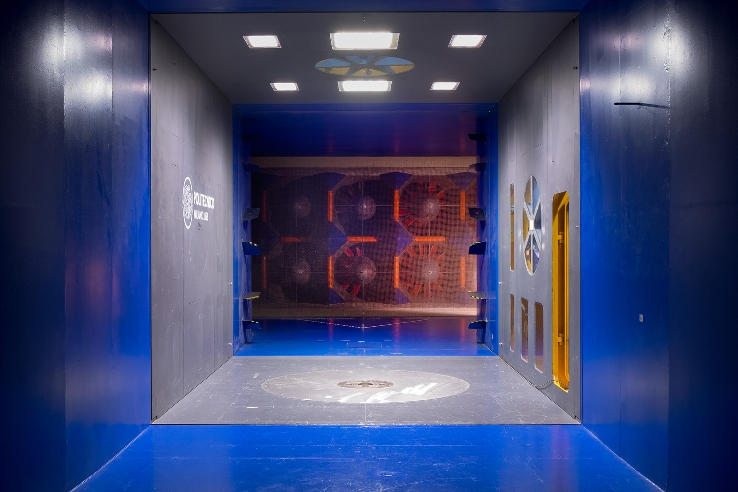
The Low Turbulence test section is 4m wide, 3.84m high and 6m long. It is possible to perform tests in a closed test section and in an open jet. The maximum wind velocity is 55m/s with a turbulence intensity below 0.1% under standard operating conditions. For applications requiring higher turbulence levels, the intensity can be increased up to 6% by installing a dedicated grid at the inlet of the test section. It is possible to remove the whole section from the airflow circuit allowing for an off-line setting-up of the test. There are two inter-changeable test sections to prepare a new experiment while the wind tunnel is running. The test section is equipped with a 2.5m diameter turntable and a traversing system behind the model’s location, suitable for wake measurements. There are several models supports equipped with a positioning system in order to vary the incidence angle. The test section is also equipped with a 3-DOF test rig that allows to move a 4m long sectional model, in along wind, cross wind and torsional directions up to a frequency of 5 Hz, while measuring acting forces by means of two multi-component force balances placed at the model extremities.
Discover our spaces
Open jet test section
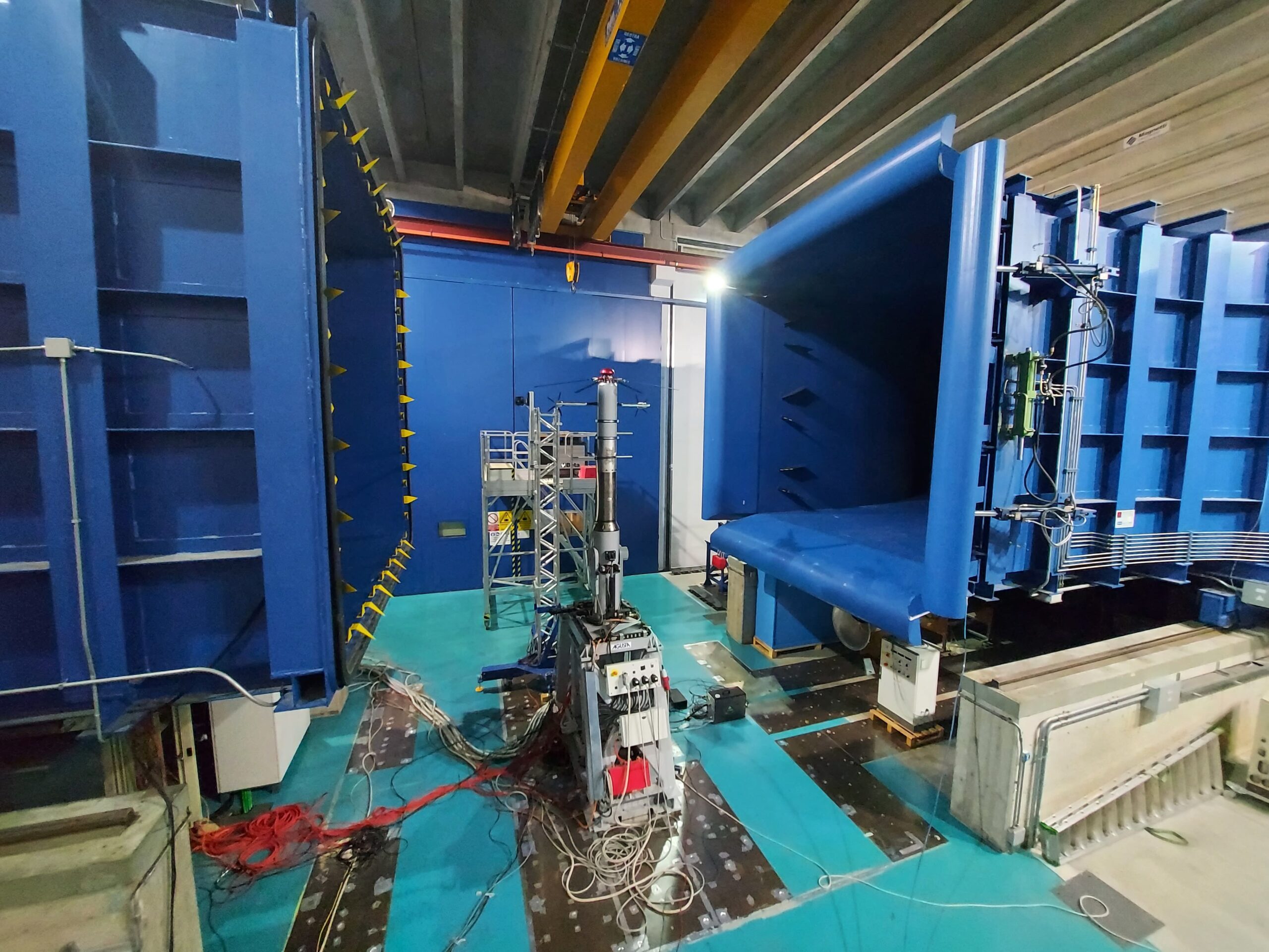
The Low Turbulence test section offers an Open-Jet mode, specifically designed for testing helicopter rotors and community wind turbines. This configuration features a jet measuring 4m wide, 3.84m high, and 5m long, capable of reaching a maximum wind speed of 55m/s. Typical research activities conducted in this setup include aerodynamic studies on helicopters, performance evaluation of small and micro vertical axis wind turbines, and testing of eVTOL propellers, particularly during the critical conversion phase. By providing a versatile testing environment, the facility supports the development of advanced flight technologies and sustainable energy solutions. The Open-Jet mode ensures high-fidelity data for complex rotorcraft configurations and urban air mobility systems, making it a pivotal resource for modern aerospace engineering and renewable energy research.
Discover our spaces
Boundary layer test section
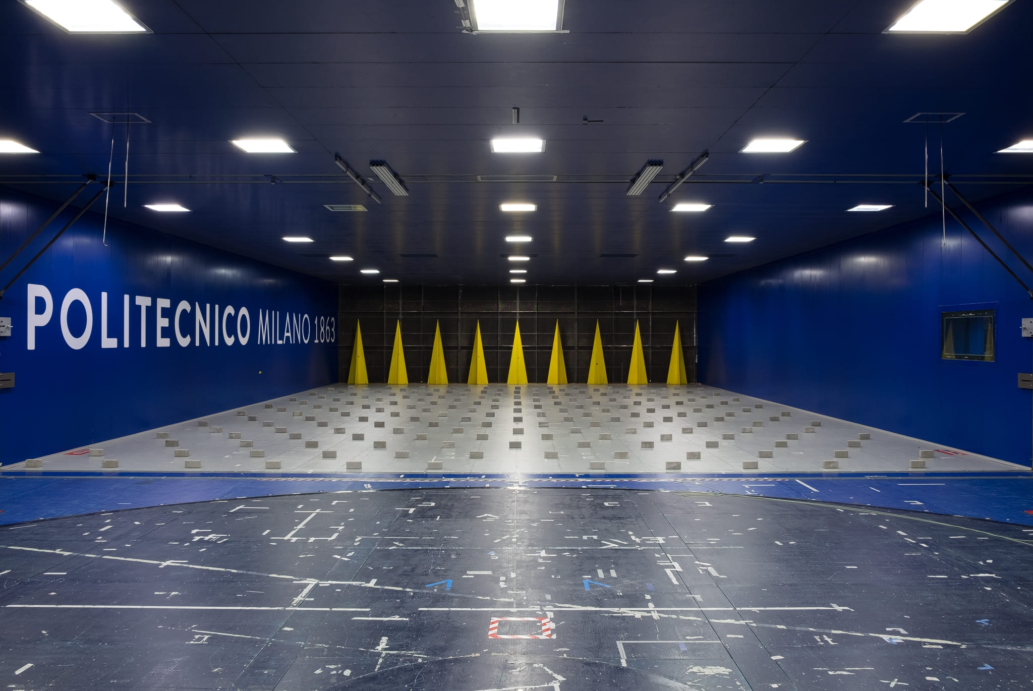
The large boundary layer test section is 13.84m wide x 3.84m high and 35 m long and is specifically designed for wind engineering tests on civil structures scaled models. The maximum wind speed is 16m/s and the turbulence index in smooth flow condition is about 2%. The constant cross-section test room enables the setting up of upstream active or passive turbulence generators to simulate the atmospheric boundary layer, with turbulence intensity that can be increased as high as 35% or even more. Several layouts of spires and floor roughness elements make possible to reproduce different terrain roughness length categories in a wide range of geometric length model scales. The model to be tested, together with the related environment, is installed on a 13m diameter turntable, embedded into the wind tunnel floor, allowing an easy change of the wind incidence angle. A floating floor allows for a clean model set-up, leaving all the instrumentation cable connections out of the flow.
Available instrumentation and devices
Our facility is equipped with advanced instrumentation to support a wide range of experiments. Explore the tools that make it possible.
Loads
measurements
Pressure
measurements
Dynamic
measurements
Flow
measurements
Device:
Bridge test rig (BTR)